DEFINITION:
A Sextant Is A Doubly Reflecting Navigation Instrument Used To Measure The Angle Between Any Two Visible Objects.
USES OF THE SEXTANT:
- Altitude Of Celestial Bodies.
- Vertical Angle Of High Terrestrial Objects To Obtain Distance Off.
- Horizontal Angles Between Prominent Terrestrial Objects To Fix Position.
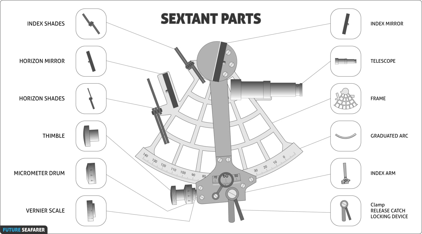
SEXTANT'S PARTS:
3D MODEL
3D MODEL
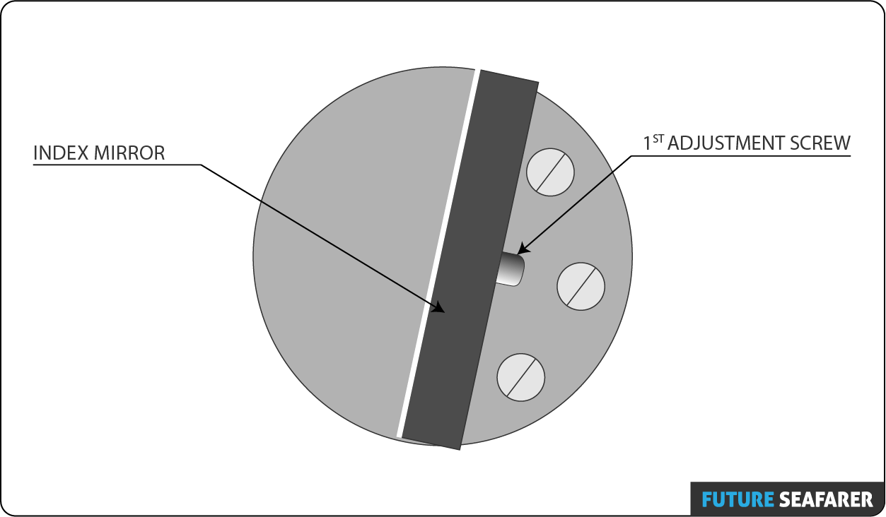
INDEX MIRROR: Is A Piece Of Silvered Plate Glass Mounted On The Index Arm, Perpendicular To The Plane Of The Instrument, With The Center Of The Reflecting Surface Directly Over The Pivot Of The Index Arm.
INDEX SHADES: Colored Transparent Substances Are Mounted On The Sextant’s Frame In Front Of The Index Mirror And Horizon Glass. They Can Be Moved Into The Line Of Sight As Needed To Reduce The Intensity Of Light Reaching The Eye.
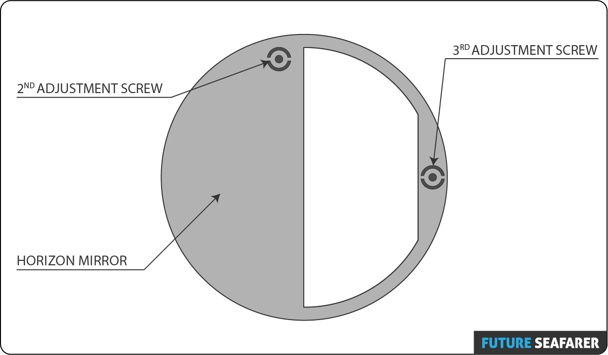
HORIZON MIRROR: Allows The Observer To View One Object Directly On One Side While Observing A Second Object Reflected Next To It. The Half Of The Horizon Glass Next To The Frame Is Silvered To Make That Portion Of The Glass A Mirror; The Other Half Is Clear Glass. It Is A Small Polished Glass Plate That Reflects Light.
HORIZON SHADES: Colored Transparent Substances Are Mounted On The Sextant’s Frame In Front Of The Index Mirror And Horizon Glass. They Can Be Moved Into The Line Of Sight As Needed To Reduce The Intensity Of Light Reaching The Eye.
TELESCOPE: Directs The Line Of Sight Of The Observer To The Horizon Glass And Magnifies The Objects Observed And Parallel To The Plane Of The Instrument.
FRAME: Structure That Serves As The Base For The Different Parts Of The Sextant.
INDEX ARM: Is A Movable Bar Of The Same Material As The Frame. It Pivots About The Center Of Curvature Of The Limb.
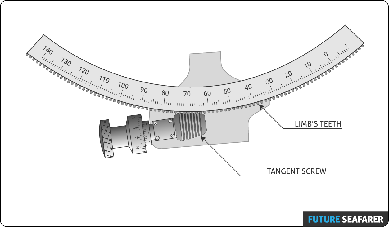
GRADUATED ARC: Indicates The Number Of Degrees Of An Angle.
MICROMETER DRUM: Rotates To Make Fine Adjustments When Measuring Angles And Indicates Minutes Of A Degree Of Angle. It Is Attached To The Lower End Of The Index Arm. One Complete Rotation Moves The Index Arm 1° Along The Arc Scale. The Drum Has 60 Graduations, Each Representing1′ Of Arc.
VERNIER SCALE: Indicates Tenths Of A Degree Of Angle. It Is Attached On The Index Arm Adjacent To The Micrometer Drum And Has10 Graduations, Each Representing 0.1’ Of Arc.
CLAMP: Is A Spring-actuated Clamp That Keeps The Tangent Screw Engaged With The Limb’s Teeth.
How Do You Take Sight?
- Put The Index Arm To Zero.
- Point The Sextant To The Horizon.
- Bring The Heavenly Body To The Horizon.
- Swing The Sextant From Right To Left To Verify That The Heavenly Body Touching The Horizon.
- Take The Reading Of The Angle.
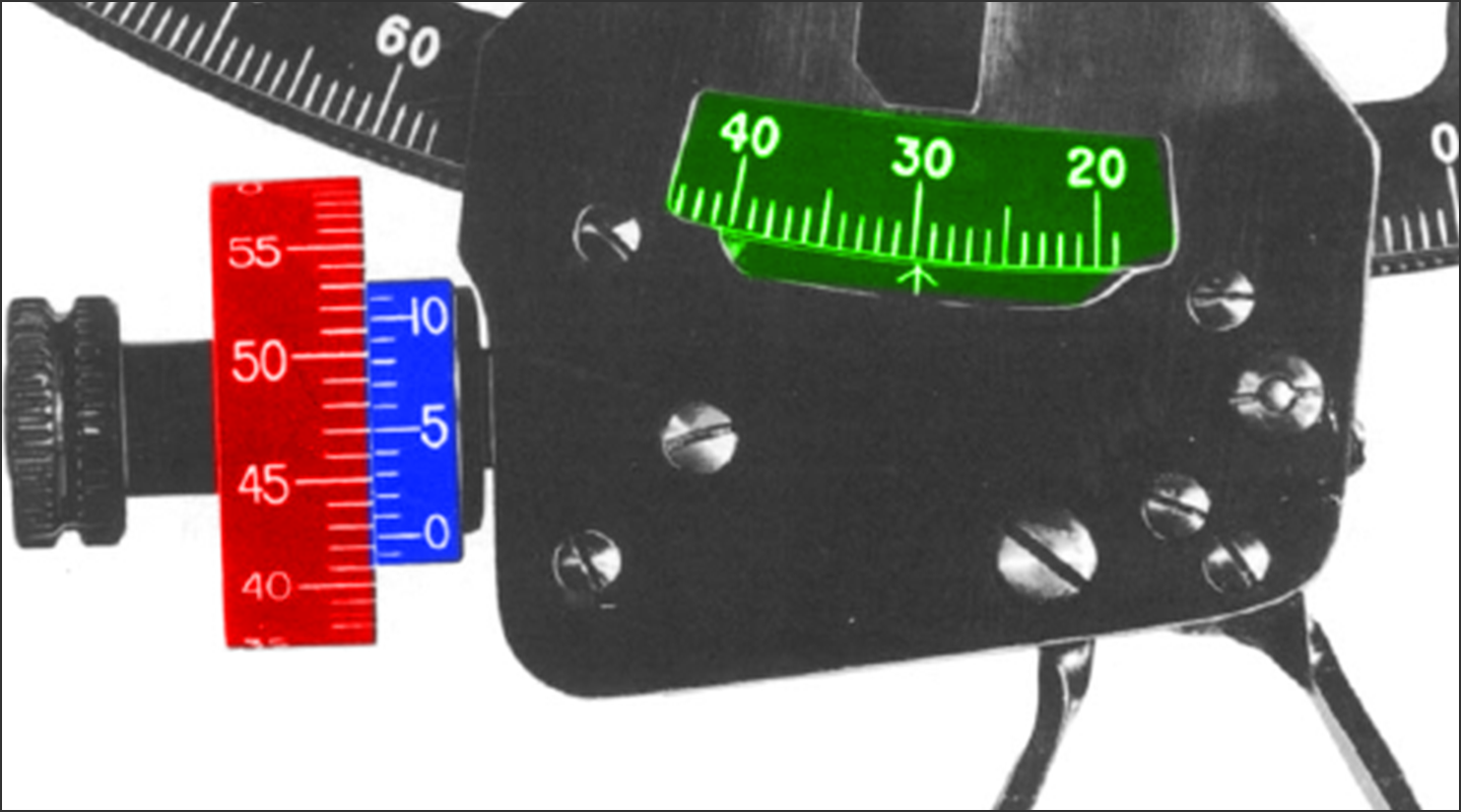
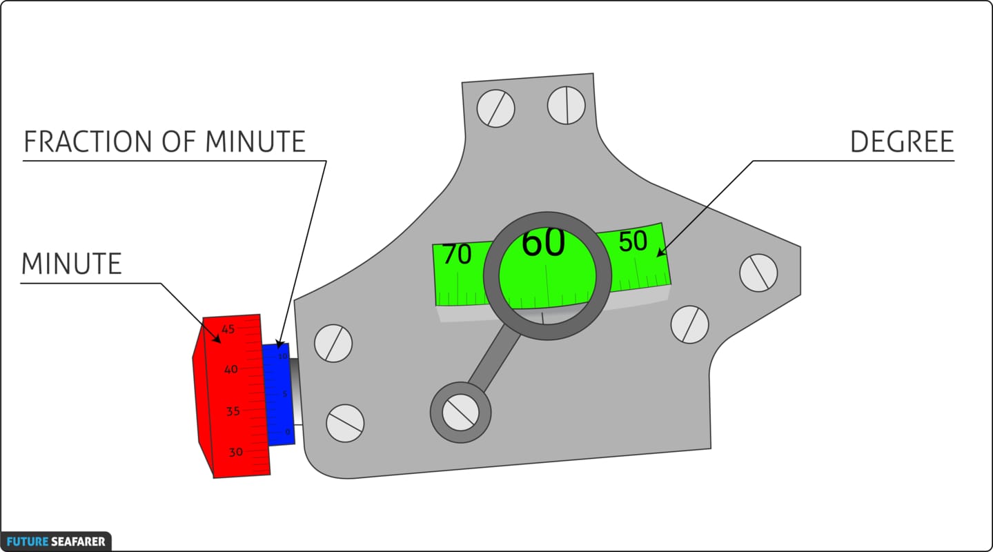
How Do You Read The SEXTANT Angle?
Reading A Micrometer Drum Sextant Is Done In Three Steps:
- The Degrees Are Read By Noting The Position Of The Arrow On The Index Arm In Relation To The Arc.
- The Minutes Are Read By Noting The Position Of The Zero On The Vernier Scale With Relation To The Graduations On The Micrometer Drum.
- The Fraction Of A Minute Is Read By Noting Which Mark On The Vernier Scale Most Nearly Coincides With One Of The Graduations On The Micrometer Drum.
Sextant Errors
There Are Two Kinds Of Errors, Which They Are:
- Non Adjustable Sextant Errors.
- Adjustable Sextant Errors.
Non Adjustable Sextant Errors
- These Error Can Not Be Fixed And Should Be Sent To The Manufacturer.
- The Manufacturer Normally Determines The Magnitude Of All Three Non-Adjustable Errors And Reports Them To The User As Instrument Error. The Navigator Should Apply The Correction For This Error To Each Sextant Reading.
Errors Types:
PRISMATIC ERROR: Is Present If The Front And Rear Faces Of The Mirrors Are NOT Parallel.
GRADUATION ERROR: Occurs In The Arc, Micrometer Drum And Vernier Of A Sextant, Which Is Improperly Cut Or Incorrectly Calibrated.
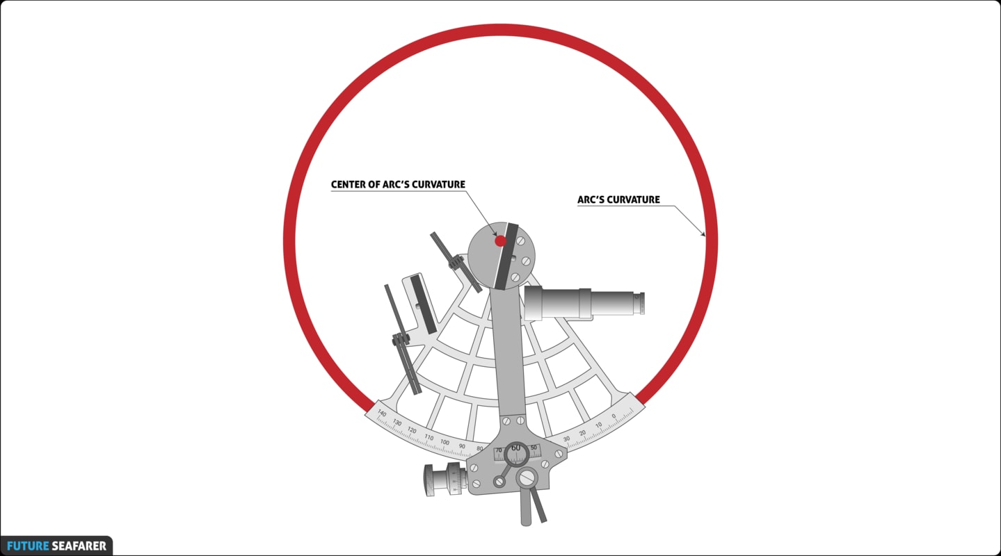
CENTERING ERROR: Results If The Index Arm Does Not Pivot At The Exact Center Of The Arc’s Curvature.
SHADE ERROR:
- Pieces Of Each Shade Exactly Parallel – If Not Shade Error Is Present.
- Shade Error Can Also Occur If The Shades Become Loose, Damaged Or Twisted.
COLLIMATION ERROR: Axis Of The Telescope Is Not Parallel To The Plane Of The Sextant.
VERNIER ERROR: When The Vernier Index Mark (Zero) Is In Coincidence With A Division On The Arc Of A Vernier Sextant, The 10 Graduation On The Vernier Should Also Be In Coincidence With A Division On The Arc, If Not Vernier Error Is Present.
WORM & RACK ERROR: Caused By Wear On The Gearing Rack.
Adjustable Sextant Errors
- These Error Can Be Adjust On-board.
Adjustable Screws:
Errors Types:
PERPENDICULARITY ERROR:
- This Is Due To The Index Mirror Is Not Being Perpendicular To The Plane Of The Sextant.
Checking The Error:
- Place Index Arm About The Middle Of The Arm.
- Hold The Sextant Horizontally With The Index Mirror Up And Toward The Eye.
- Observe The Direct And Reflected Views Of The Sextant Arc, If The Two Views Are Not Joined In A Stright Line, Then Index Mirror Is Not Perpendicular.
Removing The Error:
- Gently Turn The 1st Adjustment Screw On The Back Of The Index Mirror Until The True And Reflected Arcs Appear In A Strait Line.
SIDE ERROR:
- This Is Due To The Horizon Mirror Is Not Being Perpendicular To The Plane Of The Sextant.
Checking The Error By Horizon Observation:
- Set The Index Arm And Micrometer Exactly To 0°.
- Hold The Sextant Horizontally And Look Thru The Horizon Mirror At The Horizon.
- If True And Reflected Images Appear In A Strait Line There Is No Error.
Removing The Error By Horizon Observation:
- Turn The 2nd Adjustment Screw On The Reverse Side Of The Horizon Glass Which Is Away From The Frame Until The True And Reflected Horizons Appear In A Strait Line.
Checking The Error By Star Observation:
- Set The Index Arm And Micrometer Exactly To 0°.
- Hold The Sextant Vertically And Look Directly At The Star.
- If True And Reflected Heavenly Body Appear Side By Side, Then You Have Side Error.
Removing The Error By Star Observation:
- Turn The 2nd Adjustment Screw On The Reverse Side Of The Horizon Glass Which Is Away From The Frame Until The True And Reflected Image Pass Up And Down Directly Over The Direct View Of The Star.
INDEX ERROR:
- This Is Due To The Index Mirror And Horizon Mirror Are Not Parallel When The Index Arm Is Set Exactly To Zero.
Checking The Error By Horizon Observation:
- Set The Index Arm And Micrometer Exactly To 0°.
- Hold The Sextant Vertically And Look Directly At A Horizon.
- If Reflected And True Images Of Horizon Are Not In Strait Line, Then Index Error Is Present.
Removing The Error By Horizon Observation:
- Use The 3rd Adjustment Screw Until Both Reflected And True Images Of The Horizon Are In Strait Line.
Checking The Error By Star Observation:
- Set The Index Arm And Micrometer Exactly To 0°.
- Hold The Sextant Vertically And Look Directly At The Star.
- If Reflected And True Images Of Star Are One Above The Other The Error Is Present.
Removing The Error By Star Observation:
- Use The 3rd Adjustment Screw Until Both Reflected And True Images Coincides.
Interaction Between Side Error And Index Error:
- There Is An Interaction Between The Two Screws On The Horizon Mirror When Adjusting For The Side Error, It Is Possible To Introduce Index Error And Vice Versa.
- For This Reason It Is Necessary To Repeat The Procedure For Side Error And Index Error Until No Further Error Can Be Detected.
- Otherwise We Have To Find The Value Of The Index Error.
Finding The Value Of Index Error:
- Set The Index Arm And Micrometer Exactly To 0°.
- Hold The Sextant Vertically And Look Directly At A Star Or The Horizon.
- Adjust The Micrometer Drum Until The Reflected And True Images Of The Horizon Is In Strait Line Or Star Coincides.
- Check Now The Reading And Calculate The Error, Which They Are On The Arc Or Off The Arc.
How Will You Apply Index Error To The Sextant Reading?
- Index Error On The Arc Is Minus.
- Index Error Off The Arc Is Plus.